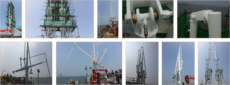
CHARACTERISTICS
STANDARD DESIGN FEATURES
- Manufacturing and Testing of Loading Arm according to the OCIMF Standards
- Designed for minimum maintenance
- Structurally supported product pipe
- Wheel Balance Type with wire ropes / Rigid Linkage Type
- Stainless Steel Hydraulic lines and fittings
- Seals available in HNBR, EPDM, PTFE or other specific materials
- Loading arm fully balanced in all positions while empty
- Manually controlled QCDC Coupler
- Support Jack
HN-MLA SPECIFICATIONS
- Arm Sizes : 3" to 24" Diameter
- Materials : Carbon Steel / Low Temperature Carbon Steel /
Stainless Steel & Other special alloys - Pressure up to : 40 bar
- Design Temperature : -200℃ ~ +200℃
- Operation Method : Manual or Hydraulic
- Main Arm Swivel Joint Styles, below
- Riser & Trunnion Swivel Joint : Style 50
- Apex Swivel Joint : Style 40
- Outboard Arm Swivel Joint : Style 80
OPTIONS DESIGN FEATURES
- Emergency Release System (ERS)
- Hydraulic QCDC Coupler
- Hydraulic Control System (HPU)
- Hydraulic Valve Block Assembly
- Electric Control System(PLC & LCP)
- Ladder & Platforms for maintenance
- Wired Remote Control(Pendant) / Wireless Remote Control(Radio)
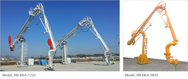
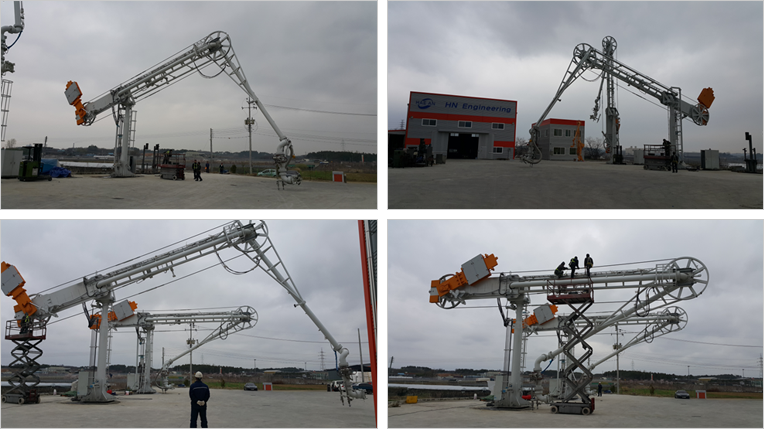
HN-MLA MODEL
HN-MLA MODEL CLASSIFICATION
| Model | Size | Base Riser | Inboard Arm | Outboard Arm | Triple Assy | Flow Rate (m3/h) |
| HN-MLA-0620 | 6" | 6000 | 9000 | 5000 | 1300 | 900 |
| HN-MLA-0820 | 8" | 7000 | 10000 | 6000 | 1400 | 1100 |
| HN-MLA-1020 | 10" | 8000 | 10000 | 7000 | 1700 | 1700 |
| HN-MLA-1220 | 12" | 8000 | 12000 | 7000 | 2100 | 2500 |
| HN-MLA-1620 | 16" | 8000 | 12000 | 7000 | 2300 | 4000 |
- Note. The unit : mm
- Note. Dimension of arms can be determined on the site conditions.
- Note. Unspecified sizes of arms can be also manufactured.
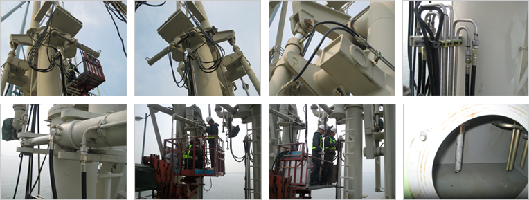
HPU & PLC & LCP
HN-MARINE LOADING ARM SYSTEM WITH HYDRAULIC & ELECTRIC CONTROL

OPERATING SYSTEM
- The control power for the arms shall be hydraulic and/or electric.
- Arms shall be maneuvered through either the fixed control panel, or through a wired/wireless remote control.
- The arm local control panel and remote control boxes shall not be operated at the same time.
- Limit Switch and Alarm for Slewing and Rotation
HYDRAULIC & ELECTRIC CONTROL SYSTEM
- Hydraulic power unit consisting of reservoir, pumps and motors, filters, relief valves, gauges and etc.
- Hydraulic Accumulator
- Emergency Hand Pump
- Emergency Release System(ERS)
- All hydraulic pipe work in loading arm
HYDRAULIC REQUIREMENTS AND COMPONENTS
- Hydraulic lines, including tube and fittings, shall be stainless steel grade 316 or 316L.
- Tube sizes should be adequately sized to provide adequate flow rated for the equipment with jetty mounted pipe work being no smaller than 10mm diameter.
- Suitable flexible hose may be used as required to provide joints or electrical insulation.
- For each arm an accumulator shall be provided to operate the ERS and loading arm to the locked position.
- Accumulators shall be sufficiently sized so that the loading arms can be maneuvered back to the parking position in the event of power failure under all operating conditions.
- When the arm parking lock is not properly engaged, a light shall be flashed at the control panel.
- The control system for the hydraulic operations of the arm may be manufacturer's standards, subject to owner's approval.
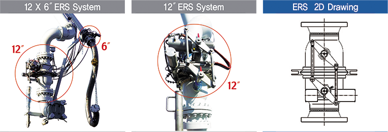
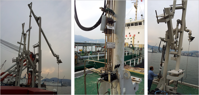
ERS SYSTEM
HN-MARINE LOADING ARM SYSTEM WITH ERS
OPERATING SYSTEM
- Marine loading arms shall incorporate an emergency release coupler in the vertical upstand of triple swivel assembly with double ball.
- ERS ensuring best possible safety in fluid loading/unloading operations with marine loading arms.
- The system allows full automatic and safe disconnection of the loading arm from the ship without product spillage, when the arm exceeds the operating envelope's limit line.
- The ERS shall be controlled automatically and manually.
- Automatically : by over-reach signal
- Manually : by push-buttons at the arm control panel and other defined shore location under healthy power condition. - The two valves shall be mechanically interlocked to guarantee simultaneous closure.
- Facilities shall be provided, either hydraulic or manual, for reopening of the valves after emergency closure.
- Control of the ERS shall guarantee valve closure prior to emergency release.
- The arrangement of the ERS assembly near the outboard end shall be such that parts of the ERS assembly remaining on board of the ship after emergency release will not fall on ship's deck or manifold service platform.
- The hydraulic cylinder operating the emergency release coupling shall be of the double acting hydraulic actuator.
- The strength of ERS shall be based on the requirements of OCIMF.
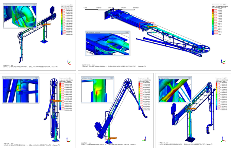
STRUCTURE ANALYSIS
STRUCTURE ANALYSIS OF LOADING ARM
- Nastran FX (or Equivalent) Software for Structural Design
- Stress Checking accordance with OCIMF
- Max. Force Calculating as per OCIMF
- Base Plate/Anchor Bolt/Wire Rope or Rigid Link/Locking Pin As per UBC code
- Lifting Method Analysis in Installation and Transportation
- Lifting Lug Check as per API & AISC ASD
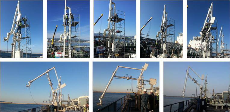
MAINTENACNE
MAINTENACE FOR MARINE LOADING ARMS
HN-MLA MAINTENANCEM
- Replacement of wire ropes

- Replacement of packing seals in swivel joint
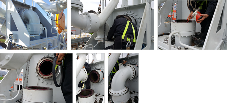
- Checking for operation in MLA (sensors, cylinders and wire ropes)
MAINTENANCE FOR OTHER MAKERS' MLA
- Korea Western Power in Pyeongtaek (Hydraulic Repair)
- SK energy in Busan (Hydraulic Valve Block Replacement)
- SK energy in Donghae (Hydraulic Cylinders Repair)
- GS Caltex in Gunsan (Outboard Arm Link Pins Repair)